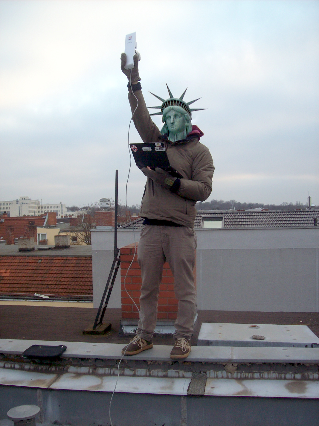
Die Freifunk-Statue / The Statue of Free Wifi
collage source by Elcobbola Our Ubiquiti NanoStationM2 kept crashing with a PoE cable of 65m Cat5e. We solved the problem by adding a capacitor. Here is how and why... Before engaging though, be aware of copper clad aluminium cable (CCA) causing higher resistance in cables. (thanks James)
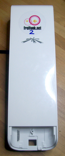

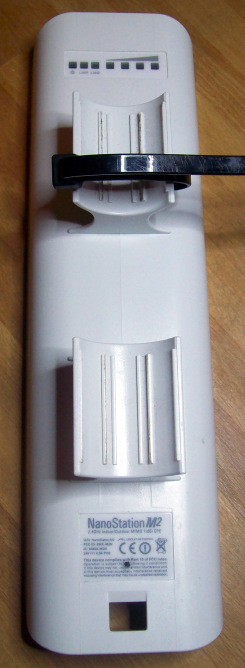
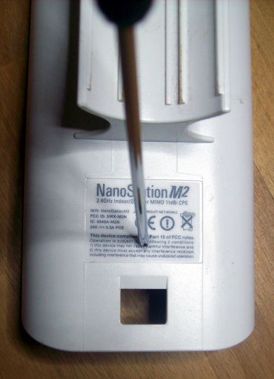
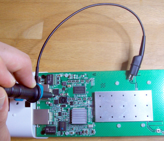
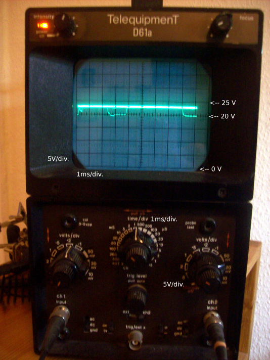
NanoStationM2 The device label says: NanoStationM2 2.4GHz Indoor/Outdoor MIMO 11dBi CPE M/N: NanoStationM2 UBIQUITI NETWORKS FCC-ID: SWX-M2N IC: 6545A-M2N 24V = 0.5A POE The Cat5e cable from the 24V 0.5A PoE adapter runs about 65m to the "Main" port of the M2. We are running an OpenWRT image from Freifunk. At the time of writing, the patched NanoStationM2 is part of Berlin's Freifunk mesh. (If you can read German, see also this excellent Zitty article.) Symptoms With a short cable, the power LED would come on alone for 15 seconds, then the rightmost LED went flashing for another 30s. After that the rightmost LED was simply on, and the wifi bubble appeared. With our long cable, however, at the point where the wifi bubble should appear, all LEDs would do a short flash, and the device would restart booting, as if power had been disconnected shortly. It would keep power cycling like this indefinitely, rebooting every 45 seconds, no wifi. With a shorter cable of 30m, the device would work without problems. But the sweet spot we were aiming for could only be reached by 65m cable. Analysis Our 30m cable has a plug-to-plug resistance of 11 Ohm, i.e. round trip 22 Ohm. At 0.5 A current, that would account for a 11 V voltage drop, with 13 V from the PoE adapter's 24 V remaining. Given that the NanoStation apparently uses two wires for each power line, it would calculate as a 5.5 V voltage drop and 18.5 V remaining. The 65m cable has 20 Ohm single pass, or 40 Ohm loop resistance. That translates to 14 V remaining (40 Ohm loop resistance divided by two wires times 0.5 A makes a 10 V drop from 24 V). The real result is probably somewhere between those 14 V and the 4 V that would remain with the full 40 Ohm loop resistance. This is getting a bit tight. We ended up opening the device and poking around in it with an oscilloscope: When the device is on a < 1m cable, the main voltage stays a solid 24V throughout operation. When powering with a 30m cable, during stable operation, we found a regular voltage drop-off pulse of almost 5V, commencing at the point where the wifi comes alive, almost 2 ms wide and cycling every handful of ms.

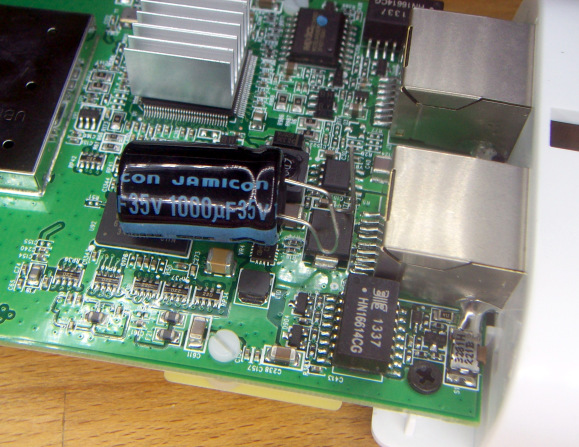
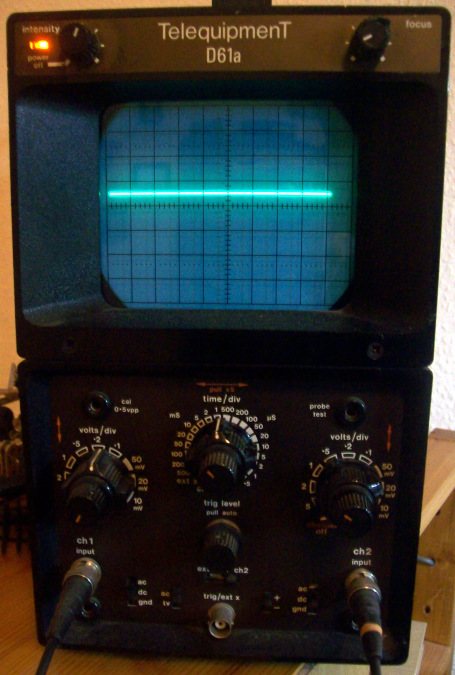
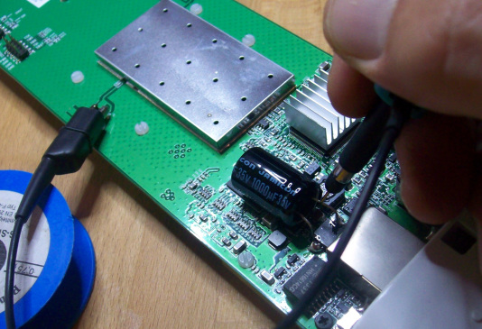
When powering with a 65m cable, the main voltage never reached above 20V. The very first voltage drop-off pulse from the wifi caused the internal 3.3 V core voltage to drop, and the device returned to boot from square 1. With a capacitance meter, we found only about 200 µF of capacitance present on the main power rail, provided by a "large" SMD-Package (presumably) tantalum capacitor. Those are very fast (low internal resistance), but very expensive with high capacitances. So it seems Ubiquiti has tried to save a bit of money on this one, compromising on long-distance PoE operation? Solution Solder a 1000 µF 35V electrolytic capacitor in parallel to the tantalum capacitor already present on the board. Even with a 65m cable, the main voltage now remains a solid line on the oscilloscope: no more drops are even detectable.
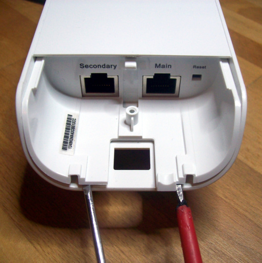
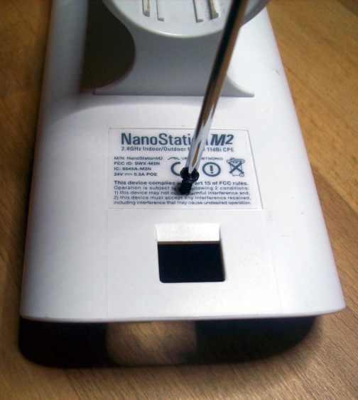
Why Imagine a large lake of water. That shall be the PoE power supply. It has all the power, say: water, that we need. From the lake runs a thin water pipe to a small basin, which is level with the lake, but quite far away. When I scoop a bucket of water from the basin, it fills up again through the pipe from the lake, only slowly. In our scenario, let's add a bomb with an air contact detonator into the water basin, floating at just above half depth. The basin must always be nearly full, or the bomb will detect contact with air and blow up. There is enough time to refill the basin between the bucket scoops. But if one single bucketful leaves too little water left in the basin, things get nasty. Either the water pipe must be wide enough to refill as quick as I take to lift the bucketful from the basin -- meaning that my cable would need very low resistance. Or my basin had better be large enough so that taking a big scoop from it won't affect its water level much. In the Ubiquiti NanoStationM2, the basin is too small to operate with such a tiny pipe -- the power rail capacitance is too low to operate with our cable's resistance. A better cable is expensive, and we already have bought the one we have here. (Check out copper clad aluminium cable (CCA) causing higher resistance in cables.) So how about just enlarging the basin... :) Instructions Needless to say that the steps described here will void the warranty. The authors can not be held accountable if these instructions end up destroying your NanoStation or anything else in the universe. Ours worked on the first try tho. If you are a bit squeamish, you may prefer buying a passive PoE adapter and plug it close to the NanoStation. Basically, this will provide the capacitance needed, with a bit of extra cost and another box dangling in the wind. Otherwise do it like this: Open the Ubiquiti NanoStationM2 casing. A screw is hidden underneath the sticker on the back, right under the bit of legalese fineprint. Take out the screw.

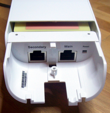
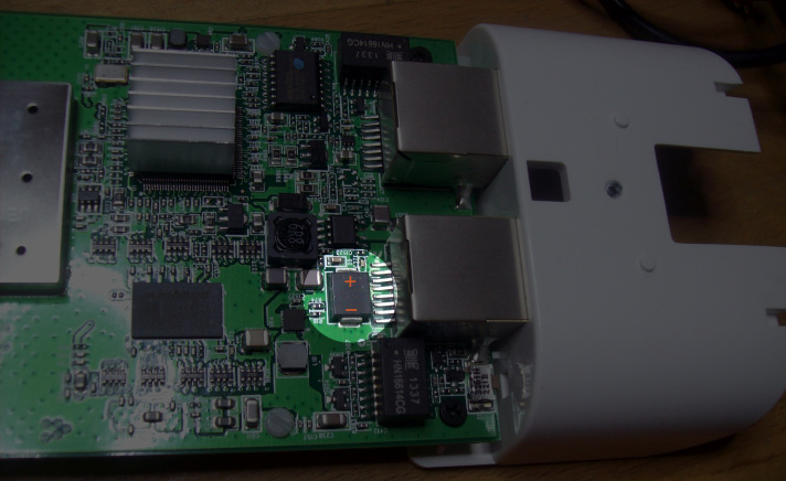
Turn around, and lift the inner plastic at the two places shown. It will then slide out with an easy comfortable pull of one finger.
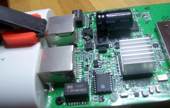
Locate the main power tantalum capacitor right behind the "Main" ethernet plug casing. During operation, you can measure the 24 V supply voltage across it with a simple volt meter. Note that its negative terminal is closer to the board edge, and the positive terminal is closer to the board center. Obtain a 1000 µF electrolyte capacitor with a sufficient voltage rating and a case thin enough to fit in the NanoStation case -- we took one rated 35 V, with a 13mm diameter. Bend its legs to easily reach the tantalum terminals. Take care to put its negative leg, marked with a large band of minus symbols, facing towards the board edge, and the positive leg toward the board center. An electrolyte cap may blow when powered in reverse.
Solder one leg on each side of the tantalum cap. Soldering may be quite hard, because both terminals are connected to a very large copper surface and they suck away the solder gun heat instantly. We had little fun until we got some help from a friendly heat gun passing by. With the electrolyte cap lying in place, melt a large blob of solder onto each of the electrolyte cap's legs so that they hang across the tantalum's terminals. Set the soldering iron to its maximum, e.g. 450 °C. The heat gun on 150 °C, first warm up the board for a minute. Now raise the heat gun to 400 °C and lowest fan speed, still aiming but keeping it ready at a distance of about half a meter. On each terminal of the tantalum cap, with the new cap's legs hanging onto it, briefly place the heat gun nozzle only a few centimeters away aiming at the soldering point, and at the same time press the 450 °C soldering iron onto the solder blob. It should melt onto the tantalum cap's terminal in very few seconds and connect nicely. Take care: Those components should be able to take heat of a couple hundred °C, but if it takes too long, you may damage components -- or they may start soldering loose from the board and shifting their positions in the wind from the heat gun (put it on lowest fan speed!). The NanoStation's white plastic casing will be the first to start warping and melting. Rather take away the heat gun and try again later if it doesn't work right away.
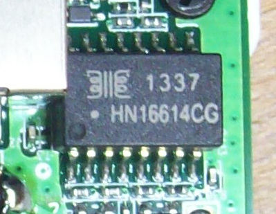
Note that our positive side solder blob also engulfs one end of the other tiny SMD capacitor located close to the positive terminal. That's fine as they are connected on the same net anyway. If you have connected any other terminals, rather get some soldering wick and clean out any unintended connections. You may also note the ugly smudges close to the soldering points. They are caused by the disintegrating flow agent in the solder and are harmless. When sliding the board back into the waterproof case, note that there are rails inside the case. If it doesn't slide in easily, you may have missed a rail in the back; try again. Put the screw back through the legalese. Plug a 100m PoE cable and test the device. Yay! Even the large chip close to our tantalum's negative terminal is impressed. It says: "1337"!
"We" We are stsp and me.


- hofmeyr.de
- about me
- OpenBSD on APU4
- vim b or tag or e
- install debian from HD
- unprivileged lxc
- debian 9
- PoE power fix for NanoStationM2
- convert DICOM xray images
- S2 pebble plug
- avr32 hello world
- pcb making
- two usbasp at the same time
- drachen
- panoramas
- rastapatch
- mved
- dddcms
- microcontroller howto
- wrist pain (RSI)
If not noted otherwise, the work on this website by Neels Hofmeyr is licensed under a Creative Commons Attribution-ShareAlike 4.0 International License.